How Is a Schematic Drawing Used
The Schematic Diagram: A Basic Element of Circuit Design
There seems to be a limitless amount of information that can be learned in the field of electrical engineering. One of the most essential skills for an electrical engineer is the ability to read and create schematics. Before you start learning Ohm's law, superposition theorem, and delta-wye transforms, you need a basic understanding of how to read (and draw) a circuit schematic.
I like the definition of schematic in Wikipedia: "A schematic, or schematic diagram, is a representation of the elements of a system using abstract, graphic symbols rather than realistic pictures. A schematic usually omits all details that are not relevant to the information the schematic is intended to convey, and may add unrealistic elements that aid comprehension … In an electronic circuit diagram, the layout of the symbols may not resemble the layout in the circuit."
When creating a schematic, it's important to make sure you're illustrating your circuit with the proper level of abstraction. If you're just trying to convey a high level concept, a napkin schematic might do the trick. If you need to create a schematic for a simulation, then the devil is in the details—you'll need to be clear about power supplies, signal sources, component values, etc. Or, if you want to create a schematic for a published paper, you'll need something polished, with the appropriate trade-off between detail and abstraction.
Schematics for Illustration
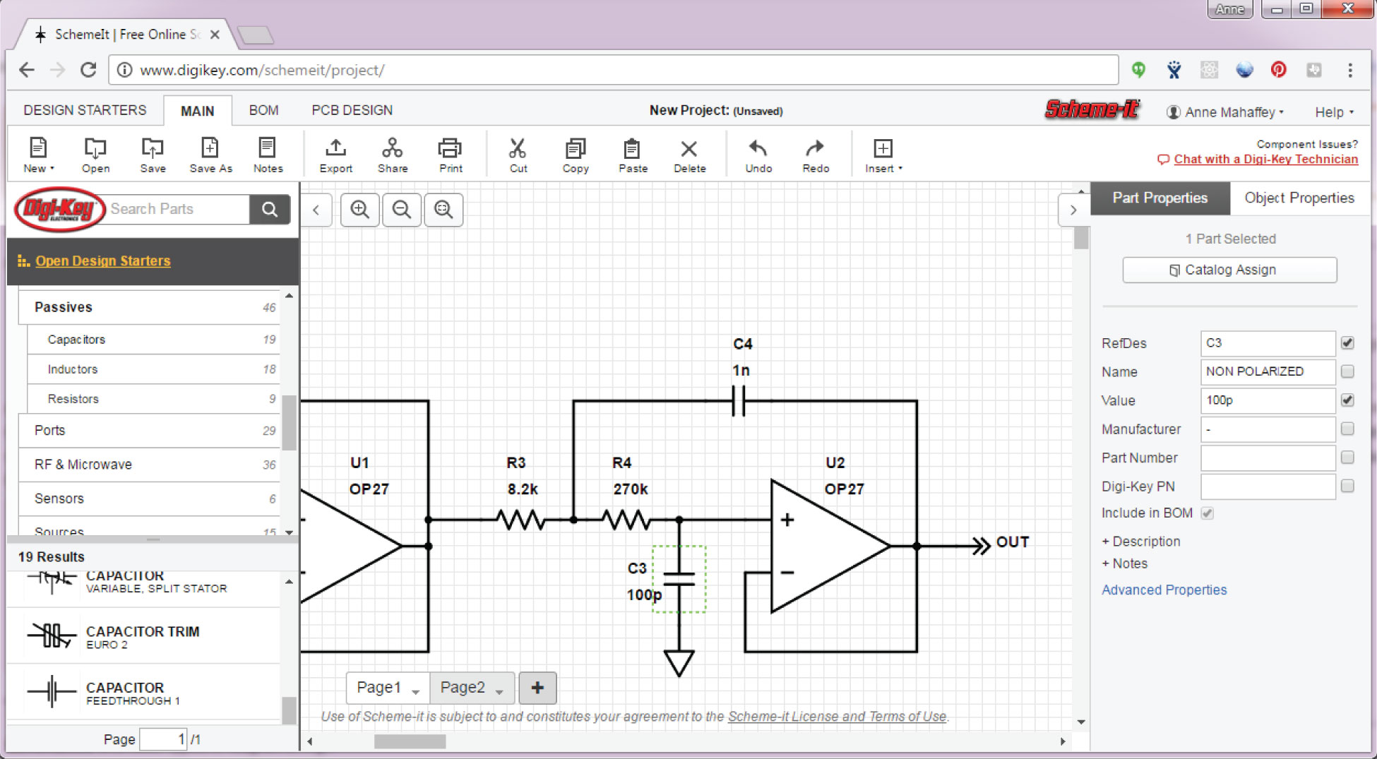
I've created schematics for a variety of reasons, and the tools I use depend on the type of schematics I'm drawing. If I'm drawing something for a report, article, or blog post, my focus is more on a presentation with a clean, professional look that doesn't necessarily include details required to simulate or build the circuit. One tool that I've had some success with is Digi-Key's Scheme-It. Since it's an EE-centric schematic tool, it's pretty quick and easy to pull together circuit diagrams. It's easy for me to add or omit labels for components, and find symbols that convey the appropriate level of detail for my diagram. For example, when searching for capacitors, I was able to find 19 different symbols.

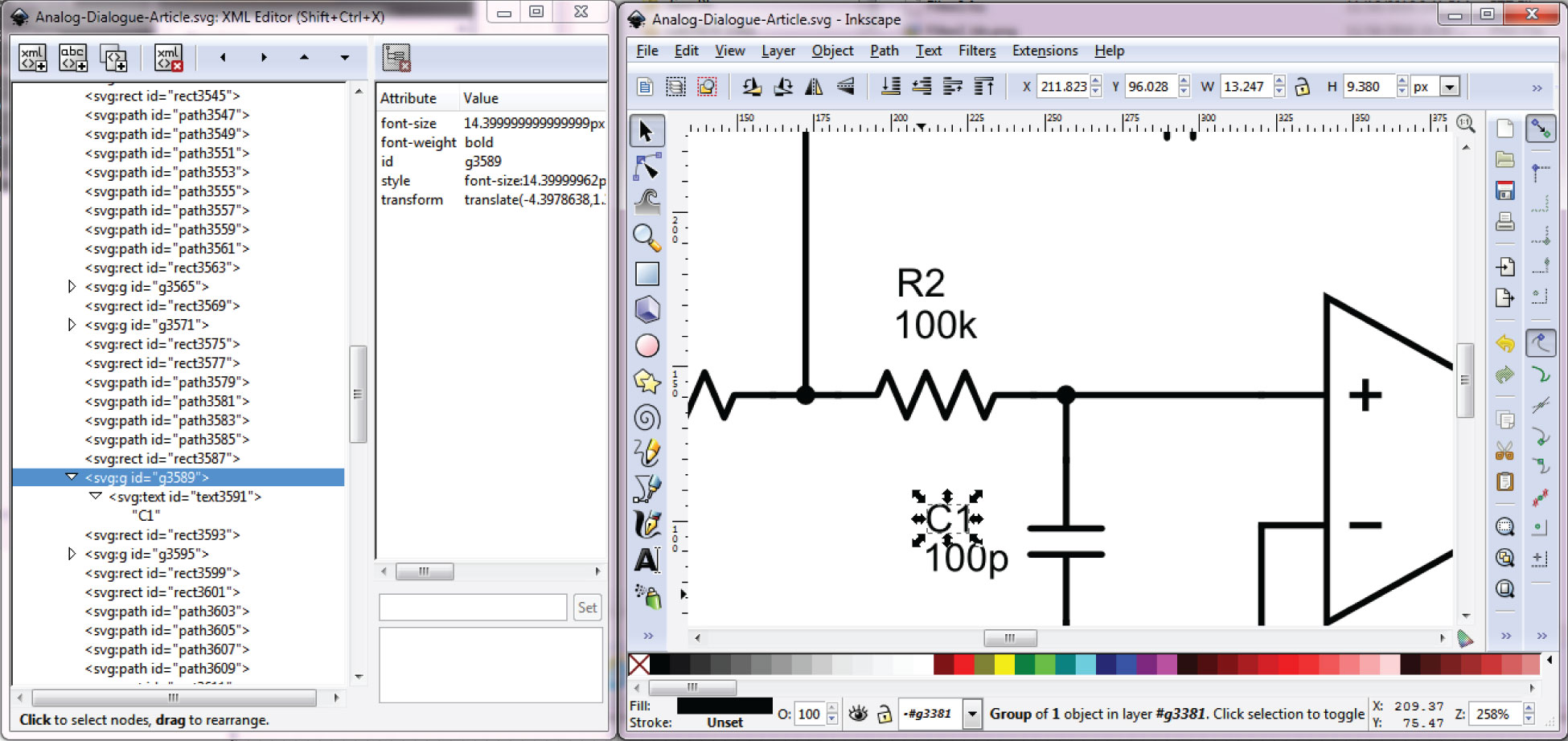
If you're having a hard time getting Scheme-It to do exactly what you need it to do, you could manually tweak your diagram by exporting it to SVG, and then editing in a tool like Inkscape or Adobe Illustrator. For example, Scheme-It wasn't lining up my nets and terminals perfectly—so I just cleaned things up in Inkscape, and exported to PNG from there.
If you want to learn more about SVG syntax, an excellent place to start is http://www.w3schools.com/graphics/svg_intro.asp. Inkscape will allow you to edit the SVG directly through the XML—if you find yourself trying to edit SVGs, it can be handy to understand the source code behind them.
Another good option for this type of schematic is Microsoft Visio. Visio is a more broad-based schematic tool, so you have to dig around a bit to find the electrical components. I've had good luck using the search feature. Visio gives me more control over my diagram—I can change line widths, colors, etc. And I haven't run into any issues where I need to go fix my diagram in another tool. But Visio has a cost and a learning curve associated with it—Scheme-It and Inkscape are a great (and low cost) starting point for drawing schematics for reports, articles, etc.

Schematics for Simulation
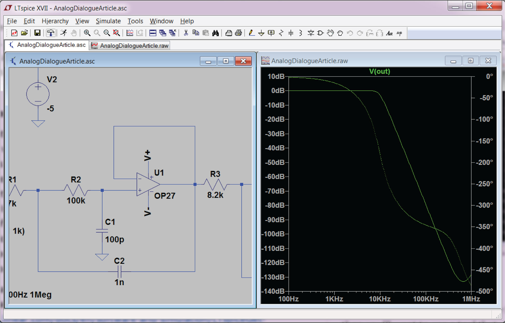
For simulation of electrical circuits, you'll need a tool that you can create a schematic with that will also have an associated netlist. For example, the netlist files that SPICE simulators use will often contain information about the diagram, as well as modeling and simulation information. Generally, you will have to get a little deeper into the specifics of the circuit in order to successfully simulate it. Instead of using a generic op amp symbol, you'll now need to specify some of the finer details: What voltages will you provide to the supply pins? Which specific op amp do you want to run your simulation with? What is the output of your circuit going to be connected to (in order to observe the effect of loading in your design)?
LTspice is a popular tool for SPICE simulation, and there's plenty of information available if you want to learn how to use it. One place to start is with the LTspice IV Getting Started Guide (PDF). But, as mentioned before, you have to get very specific about your circuit and be sure you've defined your input signal, supplies, simulation type, etc. Also, a SPICE tool is very handy for drawing and simulating analog circuits, but won't do much for you if you want to draw up a diagram for a mixed-signal or digital circuit.

Schematics for Building
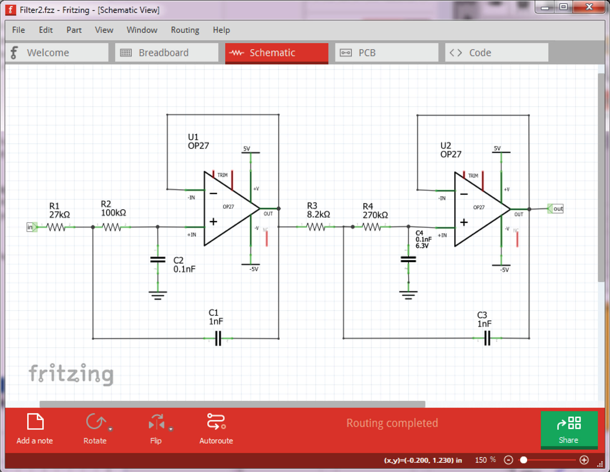
If you need to build a circuit, either breadboard or PCB (printed circuit board), then you'll want to use a tool that can link a schematic to a physical layout. Fritzing is a great choice for this—it's very easy to learn, and can handle both simple PCB layouts, as well as breadboard layouts. You shouldn't have any trouble finding tutorials for Fritizing on the web, but a good place to start is http://fritzing.org/learning/.
I usually start by building my schematic. Once I have that pulled together, I start working on the breadboard like a puzzle. This is one of my favorite things about Fritzing—it allows me to quickly see how to put my breadboard layout together before I start trimming and stripping wires.
When creating a schematic for the purpose of building a circuit, you'll notice that the tool wants to account for every pin on the device. So, in the Fritzing screenshot in Figure 4, you'll see there are some unconnected pins (in red). Because the purpose of Fritzing is to get you to a breadboard (or PCB), all physical pins are included in the symbols, even though some of the pins may not be connected to anything.

Fritzing, like most physical layout tools, syncs the schematic devices and connections with the layout view. When you build up your schematic, the breadboard (and PCB) view will display light dotted lines to indicate connections that need to be wired up.


Although I hope this was a helpful overview of a handful of schematic related tools, there are certainly many others I did not cover here. With a little digging, you'll find many other tools that might prove more useful to your project than what I've explored in this article. I'd love to hear what other tools you find useful.
And finally, a circuit quiz.
Continuing in our tradition of stimulating your thought process, this month's quiz is …

Two experiments are conducted on the same Thevenin equivalent network, and the current, i, is measured for each case. What is the Thevenin equivalent voltage and resistance of the network?
You should be able to do this in your head, but the solution is available on the StudentZone forum on EngineerZone®.
Author
fraireaginsons1946.blogspot.com
Source: https://www.analog.com/en/analog-dialogue/studentzone/studentzone-february-2017.html

0 Response to "How Is a Schematic Drawing Used"
Post a Comment